Mechanical Design
December 15th, 2023 by Matt FarmarOverall System Design
Our full-system mechanical design consists of four main components – drivetrain, chassis, soil sampler, and seed disperser – as well as miscellaneous mounts, supports, and body panels.
Drivetrain
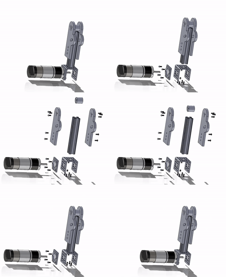
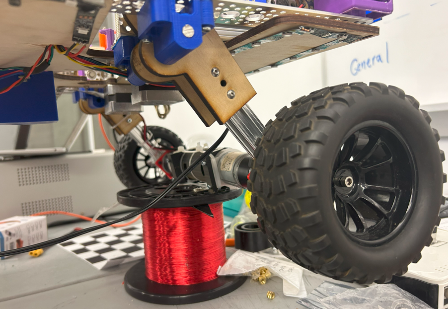
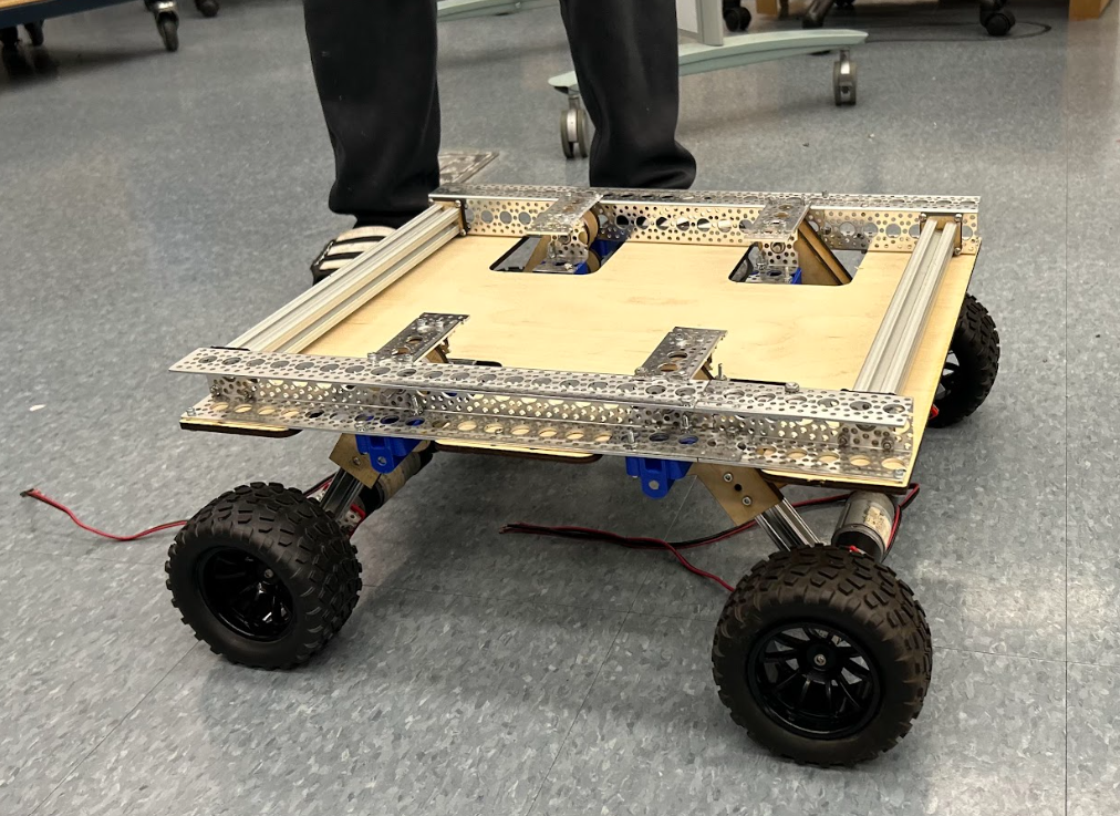
DC motors power the off-road wheels via direct drive, and the 3D printed couplers add support to counteract the cantilever caused by the length and weight of the motors. The direct drive system is mounted to our suspension arms, which can rotate along the path of a curved slot that keeps the retention pin at a fixed radius from the bearing-based rotation point.
Chassis
Our chassis is approx. 19.5” x 17” and consists of an 80-20 and C-Channel frame with a wooden laser-cut base plate. Between these three mediums, we have patterned holes, slide channels, and the capability of custom-drilled mounting holes. The 80-20 interfaces with itself perpendicularly via custom-machined 10-32 taps. The 80-20 and C-Channel connect via custom-designed, wooden interface plates that we laser cut. Finally, the C-Channel and base plate interface via 6-32 screws and nuts.
Soil Sampler
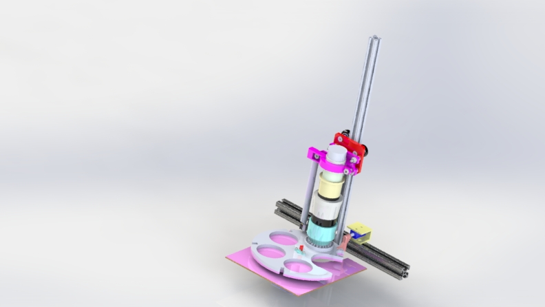
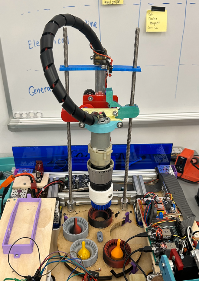
Our soil sampling assembly uses a CNC-style tool changer and retrofitted power drill to collect soil and store the samples on board the rover before swapping cartridges and repeating the process. The linear actuation for drilling and collecting the soil samples uses dual lead screws, powered by stepper motors, and an x-rail vertical track.
Seed Disperser
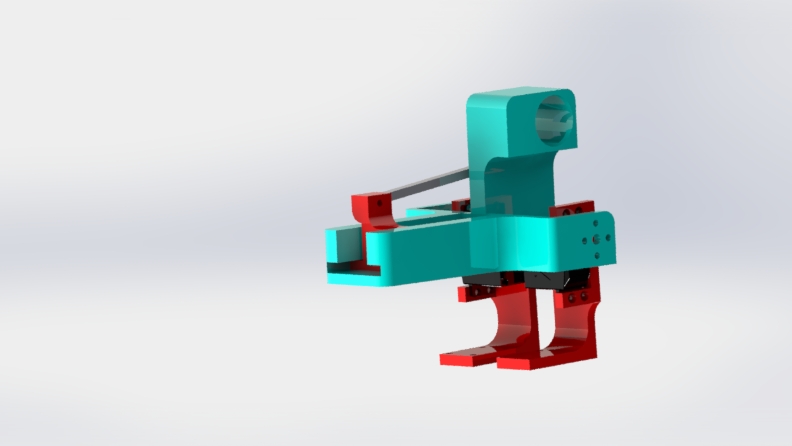
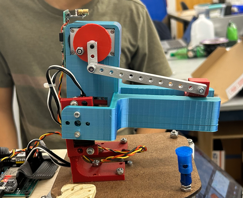
This pan-tilt system uses a stepper motor-driven lazy susan and dual servo-driven tilt actuation to aim. The dispersion mechanism uses a spring-loaded linkage to store energy before releasing quickly and launching seed in the targeted direction.
Design goals
The principal goals of our mechanical design were robustness, reliability, and adaptability. With these guiding principles, we strived for a streamlined, modular system so as to facilitate rapid iteration. Our main design goals are to maximize ground clearance and implement flexibility via suspension to help the rover overcome uneven terrain.
Design Process and Iterations
Drivetrain/Chassis
Our initial brainstorming yielded a design centered around individual suspension modules. The modules were designed with a bevel drive system so that the drive motors could be mounted vertically, with the idea being that this would maximize ground clearance by getting the body of the motors as far from the ground as possible. We also designed the infrastructure to support spring implementation to serve as suspension shocks.
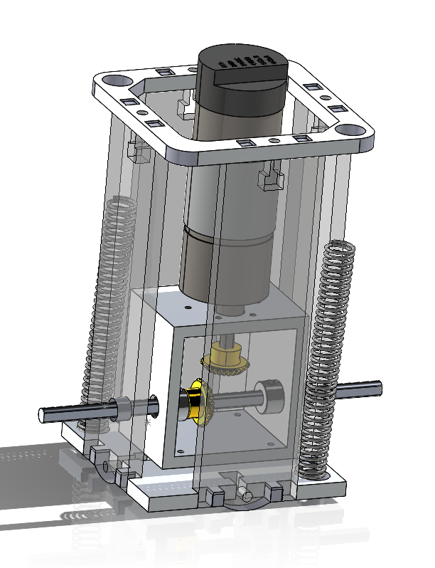
The reason behind this decision was to offer flexibility amid rough terrain, cushion jumps and falls, and help maintain traction. In mild conditions, the springs were designed to compress to a minor extent due to largely the gravitational force exerted on them by the mass of the rover. In the case of a jump, the suspension modules begin to leave the ground, and the stored energy in the compressed springs extends the wheels downward to maintain ground contact for longer than if the system were rigid. Inversely, upon landing from the jump, the springs have excess travel distance so that they absorb the impact in the form of storing gravitational energy, thus limiting the impact on the more fragile components on board, i.e. the electronics and cameras. Once at full compression, the stored energy is large enough to re-exert force downward, re-elevating the ground clearance to riding height.
In execution, we met many of our design goals but found several pitfalls through preliminary testing. The vertical motors did create extra space under the chassis base plate, but the bevel gears they required did not mesh perfectly. Based on the available budget and materials, the only accessible bevel gears and motor shaft couplers were undersized. This caused problems in the form of grinding gears and lost power. Furthermore, the structure containing the bevel gear assembly ended up being bulkier than the motors themselves, thus negatively impacting ground clearance relative to the alternative.
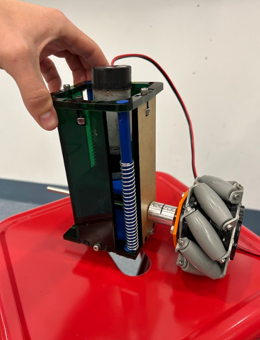
Considering these factors at the end of the first two-week sprint, we knew we had to pivot away from the design dependent upon the bevel gear assembly. Moreover, our suspension modules were cut from acrylic because it was accessible and aesthetic. After realizing how much force would be exerted on the modules during driving periods and having some of the acrylic panels crack or even snap, we knew we needed to change materials. We went back to the drawing board for sprint two, but before redesigning we wanted to evaluate our assumptions with some field research.
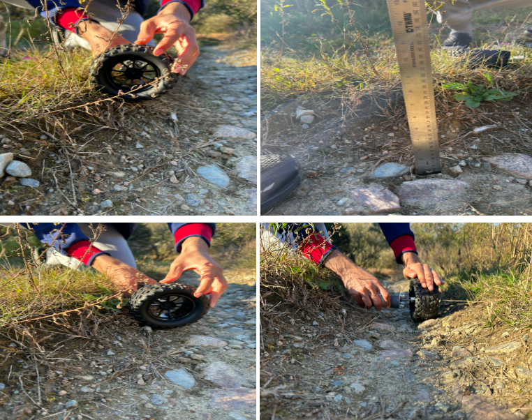
After an afternoon out in Parcel B collecting data and gaining a deeper understanding of the terrain, we revised some assumptions we made. The terrain was rough but not as steep as expected. Because the wheel diameter is much greater than that of the drive motors. We also noticed the rocks on the desired drive path were not as big as anticipated, meaning there would be no interference with changing to a direct drive system. This design change removed all our bevel gear-related problems. After building the direct drive, however, we noticed the weight of the cantilevered motors caused them to bow, so we 3D printed a coupling joint to fix them in place. During our field research, we also gained a better understanding of requisite ground clearance based on the greatest ground imbalances, which topped out at about 6-7 inches. Furthermore, we realized that our vertical suspension modules would not be practical. Since there are no big jumps, most of the force absorbed would be from the front, not directly from the bottom. This would result with a torque being exerted on the vertical system, so we redesigned the suspension to be situated at an angle to best absorb these forces.
We accomplished this by designing wooden suspension arms that can pivot about the path of a curved slot.
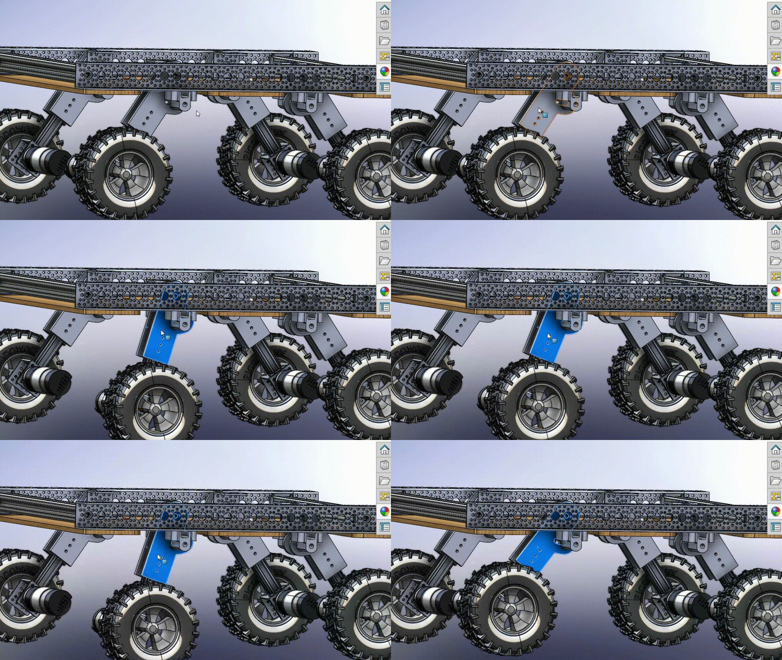
This slot allows us to control the maximum expansion and compression of the suspension system but does not use springs to dampen the oscillation.
As for our chassis, we used 80-20 and C-Channel to build a sturdy frame about 19.5” long by about 17” wide. We determined these dimensions based on what components we needed to store on the chassis base plate and how much space each would consume.
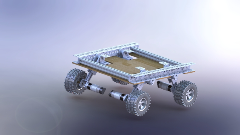
Overall, after fully fabricating the above design changes, our design was much more effective. The driving was smoother, and the rover even showed a better resemblance toward our original design inspiration, Mars Curiosity.
Soil Sampler
Our goal was to have The MuNCHER take soil samples while on off-roading missions. We wanted to design a way to take multiple samples during a mission. In order to cut down on costs, we designed the soil sampler around a retrofitted scrap power drill head and used stepper motors and x-rails that we had on hand to raise and lower it.
The initial concept was to make a design inspired by a CNC tool changer with a rotatable plate that stores multiple cartridges. The chuck fastens and unfastens by keeping the head of the drill stationary with a male gear face on the head of the drill chuck and a complementary female gear face on the cartridge slots. Then the drill spins clockwise to tighten and counter-clockwise to loosen. The drill is mounted to a linear slide with dual lead screws and the cartridge plate revolves around a stepper motor with a custom bearing. Limit switches attached to the top of the x-rail and on the path of the cartridge plate zero both systems accurately.
When manufacturing the soil sampler, we ran into the issue that the lead screws for the drill weren’t drilled precisely. We ended up laser cutting the base plate before finalizing the lead screw location due to time constraints and because of our limited amount of materials, we weren’t able to make a new one. This led us to make variable arms that attach from the lead screws to the drill. The lead screws also have elastic couplers that permit the lead screws some freedom to comply with tolerances.
These design decisions allow for the smooth operation and collection of up to four soil samples during one mission.
Seed Disperser
The seed disperser was an additional mechanism we created as a proof of concept of an eventual turret we wanted to add to the MuNCHER. The lego-inspired mechanism utilizes a spring loaded linkage to shove any item out of the channel.
This linkage utilizes a 3.3V DC motor with a torqued gearbox. This allows for ample pushing force to cock back the spring. The seed disperser is mounted on a pan/tilt mechanism. The pan aspect utilizes a Nema-27 stepper motor and a lazy susan bearing, and the tilt aspect uses two REV smart continuous servos. This subsystem was designed to be interchangeable, and potential future ideas for the existing infrastructure include a turret mechanism, robotic arm, or high powered light. The turret also includes a built in red dot laser, which is controllable via a mosfet circuit.
Body Panels and Miscellaneous Mounts
The MuNCHER uses a multitude of different processors and motor controllers (all described in more detail on the Electrical Design page), and exposing the rover’s electronic components to the harsh environmental conditions of a New England winter would spell a recipe for disaster. So, we designed and built protective body panels with an eye toward modularity and aesthetics. The first design decision to be made was the material. The major criteria were accessibility and aesthetics, given durability is negligible considering the pieces are not structural in any way, so we chose blue acrylic.
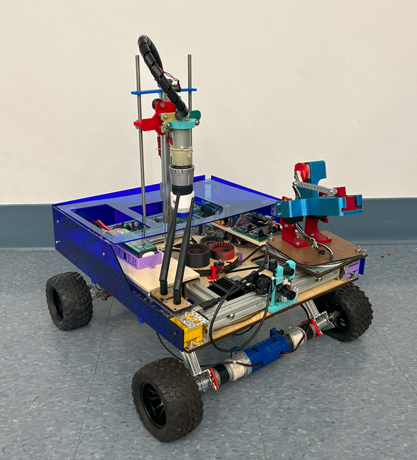
This balance between form and function protects our valuable and hydrophobic electronics while encasing the rover with translucent colored panels that allow you to still see the inner workings of the system.
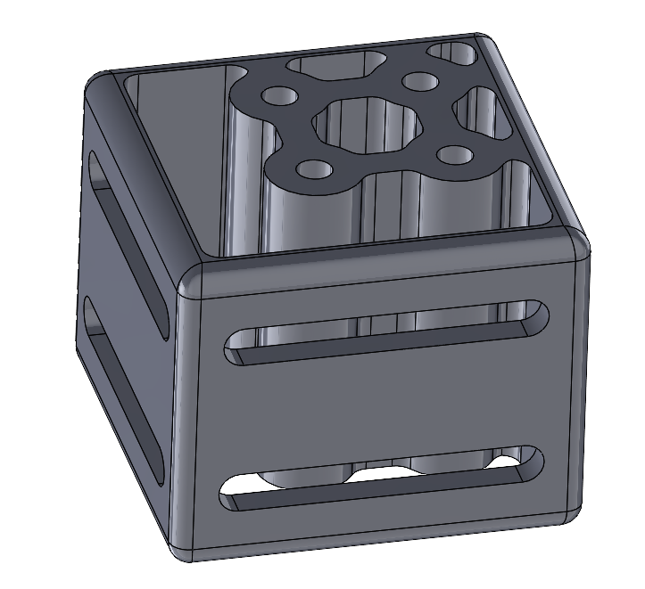
From a mounting perspective, we wanted to focus on modularity and adaptability. For the body panels, this meant mounts that could attach at many different places. The C-Channel we use around the perimeter of the chassis has a repeating pattern, so we 3D printed rectangular prism mounts that sit in the C-Channel and can attach at mounting holes anywhere along the length of the piece. This design flexibility helps with fabrication accessibility because we can avoid interferences with the other screws and wires running through the channel. To further support design flexibility, our body panel mounts have ovular slots where the body panels attach so that the body panels can be optimized with minor adjustments post-fabrication.
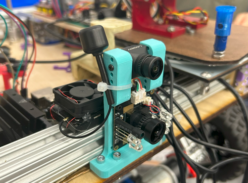
Similarly, we wanted adaptability for our camera mounts. We knew the general area of where to best mount them, but for optimized performance we added several sets of mounting holes so that we could test different positions without redesigning the 3D print.
Finally, and perhaps most importantly, our limit switch mounts. We use three of them: one for the soil sampler upper limit, one for the soil sampler tool changer, and one for the turret-based seed disperser. The mounts needed to be sturdy but did not need to withstand great force; the only critical design consideration was ensuring there were no undesired interferences with moving parts.
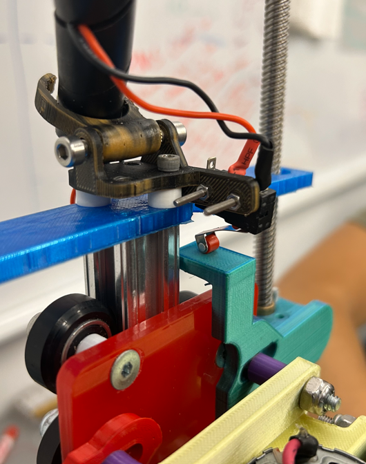
The limit switch shown above is the soil sampler upper limit.
Considerations for Future Work
Drivetrain/Wheel Improvements
Our current motor-wheel assembly functions as intended but has room for improvement. The main problem right now is power loss while turning due to high friction between the wheels and the terrain. The original design goal was to maximize traction, so we used extremely soft wheels padded with flexible foam inserts to maximize the ground contact patch. We ended up being too successful in increasing friction, in fact, because tank steering couldn’t turn smoothly and even differential drive wasn’t ideal. To resolve this issue moving forward we would change the wheel softness by adding solid inserts or using different wheels entirely. This change would decrease the area of the contact patch and therefore decrease friction to make turning easier.
Mechanical Design improvements
A major issue with the drivetrain is the robustnes. The drivetrain is well put together and as mentioned earlier, functions as intended, but there were many design choices we made in the fabrication that contribute to the issues specified earlier. Firstly, since our axle couplers were drilled out to be a larger size for a design change in sprint 1, we had to add tapped set screws in each of the couplers, and this had an adverse effect of making our axles not entirely concentric. For future improvements, we would need completely new axle couplers, as the current ones have been overmodified. Another issue lies in the 3d printed motor coupler. This design decision accounted for using 4 milled Motor clamps, but in it’s current state, uses 3 milled pieces and 1 3d printed clamp due to us losing one of our clamps. This motor coupler has made the legs of our drive training move slightly outward, which increases the sag of the overall drivetrain.
Weatherproofing
Our body panels were made to be adjustable and therefore show gaps at the corners and intersections. As a temporary solution for outdoor driving, we used trash bags as waterproofing, but we will look toward more permanent solutions. If we were to redesign we would make the body panels more precisely dimensioned so the gaps are smaller and could be filled more easily.
