Electrical Design
December 15th, 2023 by Ian WalshDesign Goals
The electrical system was designed to be modular, efficient, and rugged–especially under heavy loads. Power circuitry was designed to isolate MCU/logic from large inductive loads like the drivetrain and soil sampler, and attention was paid when routing data cables around the robot.

Implemented Solutions, Decision Explanations, and Iterations
Power System
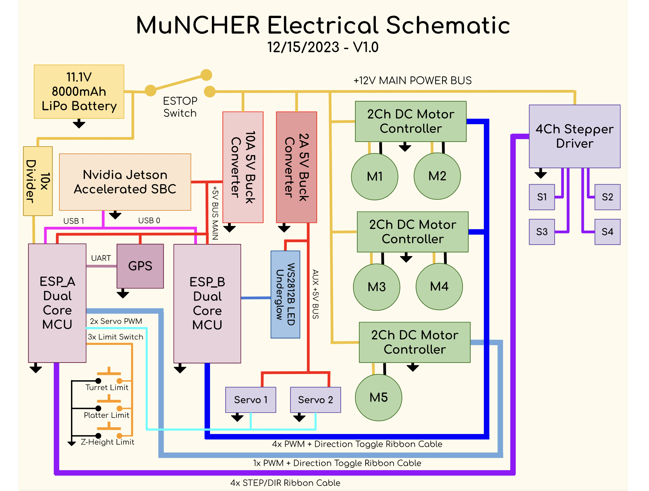
The MuNCHER’s electrical supply system can be divided into three parts:
- Unregulated +12V supply. This supply is connected directly to our power source: a 3S 8000mAh Lithium Polymer battery rated for upwards of 400A momentary discharge. This bus is monitored by a voltage warning/cutoff system and can be shut off in an instant by an ESTOP safety feature. The bus is responsible for powering the high-current DC motor controller stack and four stepper motor drivers as well as the two regulated 5V buses.
- +5V logic supply. This bus is a tap of the main +12V bus, regulated to 5V by a 10A buck converter. This bus powers the Nvidia Jetson MPS (Motion Planning System ®) and the two ESP32 I/O controllers. This bus was purposely oversized and isolated from the rest of the system to supply the logic units with clean uninterrupted power.
- +5V I/O supply. Again a tap of the main +12V bus, the I/O supply’s core is a smaller 3A peak switching converter. It is responsible for powering aux features like RGB LED underglow and the turret’s servo motors.
Soil Sampler Electrical
The soil sampler has steppers, limit switches, and a large DC motorized drill as electrical components. Occupying three of the four stepper motor controllers, the soil sampler is the most complex electrical system on the rover. The auxiliary ESP32 (ESP_A) is the brains of the operation here, monitoring limit switches on both the Z-stage and platter for auto-zeroing functionality, controlling the drill motor speed (PWM), and interacting with the stepper controllers. The two zeroing limit switches are configured NO (normally open) with 30k pullup resistors.
One issue that we faced was making sure the limit switch for the cartridge plate was mounted in such a way that would get triggered but also allow the plate to rotate freely. We decided to make the plate only rotate counter-clockwise as this allowed us to engineer a limit switch that actuated smoothly every time.
Drive Motors
The Drive system works on the +12 main bus. Three dual-channel PWM DC motor controllers were used to control four drive motors and one drill motor. The controllers have a peak current of 20A and a continuous rating of 10A which is more than enough for each DC motor. Each controller is directed by two pins from the ESPs: 8-bit 1000Hz PWM for speed control and a digital value for direction (a logic HIGH represents reverse and logic LOW represents forward).
Camera System
The robot contains two camera systems. One is a generic USB camera that is used by the Nvidia Jetson for robot navigation. The other is a FPV camera that transmits its image to an AR headset worn by a user.
Seed Dispenser
The seed dispenser uses a NEMA-27 Stepper motor, two REV Servo Motors, a 3.3V DC motor, a limit switch, and a red dot laser in terms of electrical components. The Limit switch sets the 0 position of our stepper pan mechanism. All of the components are connected to IO pins on the ESP-32+++++.

Considerations for Future Work
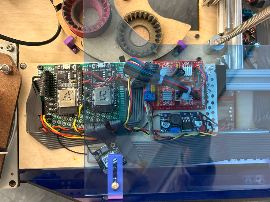
We would like to reorganize where the Jetson Nano is located as well as reorganizing some of the wire runs. The Jetson Nano is currently placed on the bottom plate which makes it susceptible to damage from water and mud. It also has many cables that go into it and is cramped when in such a small slot. For the future, we would like to relocate the Jetson Nano to a higher level on the rover.